Category Archives: ESD Information

The importance of Periodic Verification – Part 1
Today we want to talk about a subject many users forget about when it comes to ESD protection: periodic verification.
Whilst many people understand the basic concepts of ESD and as a result insist on a properly equipped ESD Protected Area (EPA), they then forget all about it. They use the same products day-in, day-out, year after year, without knowing if their products are actually still working properly.
So today we want to look at the most common products in your EPA that you should be checking on a regular basis. And because there are quite a few product groups to discuss, we have split this post in 2 parts – we don’t want to scare you away with a never-ending blog post…
Why periodic verification?
Each component in an ESD protected area (EPA) plays a vital part in the fight against electrostatic discharge (ESD). If just one component is not performing correctly, you could damage your ESD sensitive devices potentially costing your company money. The problem with many ESD protection products (think wrist straps!) is that you can’t always see the damage. Just by looking at a coiled cord that has no visibly damage to the insulation you would not know if the conductor on the inside is damaged. That’s where periodic verification comes into play.
ESD protected area (EPA) products should be tested:
- Prior to installation to qualify product for listing in user’s ESD control plan.
- During initial installation.
- For periodic checks of installed products as part of IEC 61340-5-1 Edition 1 2007-08 clause 5.2.3 Compliance verification plan.
It’s #3 we will be focusing on in this 2-part series.
Worksurface Matting
The purpose of ESD bench matting is to ensure that when charged conductors (conductive or dissipative) are placed upon the surface, a controlled discharge occurs and electrostatic charges are removed to ground. However, this only occurs if the ESD work surface is actually connected to ground. If the matting is out-of-spec, not grounded at all, the stud on the mat has become loose or the ground cord has become disconnected, charges cannot be removed.
Many companies use a daily checklist, which includes the operator having to verify that ground cords are firmly connected.
Remember to regularly clean your bench matting to maintain proper electrical function (e.g. Reztore Surface and Mat Cleaner). Do not use cleaners with silicone as silicone build-up will create an insulative film on the surface.
The company’s compliance verification plan should also include periodic checks of work surfaces measuring:
- Resistance Point-to-Point (Rp-p) and
- Resistance-to-ground (Rg).
 Testing a working surface using 99026
Surface resistance testers can be used to perform these tests in accordance with EN 61340-5-1 Electrostatics and its test method IEC 61340-2-3; if these measurements are within acceptable ranges, the worksurface matting and its connections are good.
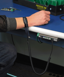
Wrist Straps
As discharges from people handling ESD sensitive devices cause significant ESD damage, the wrist strap is considered the first line of ESD control.
Before handling ESD sensitive items, you should visually inspect the wrist strap to see if there are any breakages etc. The wrist strap should then be tested while worn using a wrist strap tester. This ensures all three components are checked: the wrist band, the ground cord (including resistor) and the interface with the wearer’s skin. Records of each test should be kept. Wiggling the resistor strain relief portion of the coil cord during the test will help identify failures sooner. Analysis and corrective action should take place when a wrist strap tester indicates a failure.
 Checking wrist straps using 99031
It is recommended that wrist straps are checked at least daily. An even better solution to daily wrist strap checks is the use of continuous monitors. They will alarm if the person or work surface is not properly grounded.
A note on worksurface matting and wrist straps: if you are using earth bonding points, earth bonding bars etc. to ground the operator and/or bench matting, remember to inspect and test those regularly as well (every 6 months for example).
Keep your eyes peeled for our follow-up post.

4 Reasons you should consider Continuous Monitoring
Wrist straps are considered the first line of ESD Control. They are used to link people to ground which ensures that that the operator is kept at the same potential as surfaces, objects and ESD sensitive devices. Wrist straps need to be visually inspected and checked (while worn) on a daily basis – BEFORE handling any ESD sensitive item. This will alert the operator if their wrist strap has developed a fault and as a result does not ground them any longer.
An alternative to periodic testing is the use of continuous monitors. Per ESD Handbook TR 20.20 paragraph 5.3.2.4.4 Test Frequency, “Because wrist straps have a finite life, it is important to develop a test frequency that will guarantee integrity of the system. Typical test programs recommend that wrist straps that are used daily should be tested daily. However, if the products that are being produced are of such value that knowledge of a continuous, reliable ground is needed, then continuous monitoring should be considered or even required.”
In today’s post we will highlight 4 benefits of continuous monitoring which may help you decide to move away from daily wrist strap checks.
But first a little reminder of what continuous monitors actually are: Continuous monitors come in different styles and sizes but are intended to be kept on your workstation. Some units just ‘sit’ on your bench; others are attached to your working surface matting; some can even be attached underneath the workbench so they don’t take away valuable workspace. Operators connect their wrist strap to the unit to allow for real-time continuous monitoring. If the wrist strap fails, the unit will alarm. Many continuous monitors also feature a parking stud providing a means for the operator to disconnect when leaving their workstation.
There are two different types of continuous monitors available:
- Single-wire continuous monitors allow the use of any standard, single-wire wrist strap and coil cord. The monitor / wrist strap system life-cycle costs are significantly lower than dual-wire systems. While they would not be suitable for the most critical applications, single-wire continuous monitors are an economical way to monitor both the operator’s wrist strap and/or workstation surface.
- Dual-wire constant monitors provide true continuous monitoring of wrist strap functionality and operator safety according to accepted industry standards. Dual-wire continuous monitors provide redundancy because even if one dual-wire wrist strap conductor is severed, the operator still has a reliable path-to-ground with the other conductor.
1. Instant Feedback
Imagine this scenario: you come to work in the morning, you test your wrist strap, it passes and you start work on your ESD sensitive devices. 3 hours later, when you come back from your tea break, you test your wrist strap again and it fails. What to do? You don’t know if the wrist strap only just failed or if it failed right after your first test in the morning. How do you know if the devices you worked on all morning have been damaged? You don’t – after all, latent defects are not visible and failures may only occur at a later time. Using continuous monitoring while working on those ESD sensitive devices will alert the operator as soon as their wrist strap fails. The faulty wrist strap can be replaced with a new model from stock and everyone is happy – no ESD sensitive devices damaged and no unhappy customers.
The EMIT Zero Volt Monitor (50579) in Use
Continuous monitors provide operators with instant feedback on the status and functionality of their wrist strap. The instant an operator’s wrist strap or cord fails, the monitor will issue audible and visual (LEDs) alarms alerting the user and supervisor of the problem. Full time continuous monitoring is superior to periodic or pulsed testing, and can save a significant amount of money in testing costs and rejected product. Periodic testing only detects wrist strap failures after ESD susceptible products have been manufactured. The costs of dealing with the resulting catastrophic failures or latent defects can be considerable. “A properly grounded wrist strap will keep a person’s body voltage to approximately + 10 V. The main advantage to a constant [or continuous] monitor is the immediate indication that the employee receives if the wrist strap falls open. With an unmonitored system, the employee will not be aware of a wrist strap failure until the start of the next shift. This has reliability benefits for an ESD program as it might help reduce or eliminate ESD damage.” [CLC/TR 61340-5-2:2008 User guide Annex B.1.3 Constant monitors].
2. Monitor Operator AND Workstation
An option available with most continuous or constant monitors is the ability to monitor working surface ground connections. “Some continuous monitors can monitor worksurface ground connections. A test signal is passed through the worksurface and ground connections. Discontinuity or over limit resistance changes cause the monitor to alarm. Worksurface monitors test the electrical connection between the monitor, the worksurface, and the ground point. The monitor however, will not detect insulative contamination on the worksurface.” [ESD TR 12-01 Technical Report Survey of Constant (Continuous) Monitors for Wrist Straps]
When the monitor is connected to an ESD Mat working surface, the amount of current that flows is a function of the total resistance between the monitor and through the working surface to ground. When the resistance of the working surface is below a pre-set threshold*, the monitor will indicate good. Conversely, if the resistance level is high when compared to the monitor’s reference*, the unit will alarm. This is an integrating resistance measuring circuit, therefore it is relatively insensitive to externally induced electromagnetic fields.

Installing the Charleswater Multi-Mount Monitor (99129) to ground the worksurface
“For units that also monitor the connection of a worksurface to protective earth, it is also possible to reduce or eliminate the checking of the worksurface as part of the periodic audit of the process.” [CLC/TR 61340-5-2:2008 User guide Annex B.1.3 Constant monitors].
*The resistance threshold limits can vary between brands and models (and can sometimes also be adjusted by the user) so make sure you do your homework before committing to a particular unit and check the limit meets your individual requirements.
3. Detect Initial Flex Fatigue
Unlike wrist strap testers, continuous monitors detect split-second failures when the wrist strap is still in the “intermittent” stage. This is prior to a permanent “open” which could result in damage to ESD sensitive components.

The Jewel Mini Workstation Monitor (99135) in Use
“Wrist strap checkers are usually placed in a central location for all to use. Wrist straps are stressed and flexed to their limits at a workstation. While a wrist strap is being checked, it is not stressed, as it would be under working conditions. Opens in the wire at the coiled cord’s strain relief are sometimes only detected under stress.” [ESD TR 12-01 Technical Report Survey of Constant (Continuous) Monitors for Wrist Straps]
4. Eliminate Need for Periodic Testing
Many customers are eliminating periodic touch testing of wrist straps and are utilising continuous monitoring to better ensure that their products were manufactured in an ESD protected environment. Continuous monitors eliminate the need for users to test wrist straps and log the results; by their function, these monitors satisfy the EN 61340-5-1 test logging requirements. “There are also other process benefits from using constant monitors such as the elimination of the need to maintain daily test logs and a reduction in the time for employees to make the daily test.” [CLC/TR 61340-5-2:2008 User guide Annex B.1.3 Constant monitors].

No more Paper Logs!
So when using constant monitoring, operators:
- Don’t have to waste time queuing at a wrist strap test station before each shift.
- Don’t have to remember to complete their daily test logs.
It’s also harder to ‘cheat’ with continuous monitors. We’re not saying, your employees would do naughty things like that but we’ve seen it all before: operators ‘pretending’ to perform a wrist strap check, operators failing a wrist strap test and still recording a pass etc. There are always options to bypass a system, but it’s definitely harder when continuous monitors are used.
So should you now run-out and equip all your users with continuous monitors? As with most things in life, the answer is not that simple: it depends! If your company manufactures products containing ESD sensitive items, you need to ask yourself “how important is the reliability of our products”? Sooner or later a wrist strap is going to fail. If your products are of such high value that you need to be 100% sure your operators are grounded at all times, then you should consider a continuous monitoring system.

The importance of ESD safe tools and accessories – Part 1
So you finally have your ESD Protected Area (EPA) in place – you’ve invested in ESD working surface & floor matting, provided wrist straps & foot grounders for your workers and you control access to your EPA. But still: you are experiencing a large number of failures when inspecting your components after the production stage. The reason may be simpler than you think. Read on to find out more.
Conductors and Insulators
Materials that easily transfer electrons (or charge) are called conductors and are said to have “free” electrons. Grounding works effectively to remove electrostatic charges from conductors to ground.
Materials that do not easily transfer electrons are called insulators or non-conductors. An insulator will hold the charge and cannot be grounded; therefore, the charge cannot dissipate in a controlled way. This could lead to static damage of nearby sensitive components as there can be a rapid, spontaneous transfer of electrostatic charge.
So how do you control static electricity in the workplace? Easy – just follow these principles:
- Remove all unnecessary insulators (non-conductors),
- Replace all non-conductive materials with dissipative or conductive materials and
- Ground all conductors.
So what insulators in your EPA can be replaced with dissipative or conductive materials? Here is a list of the most commonly used insulative items and their replacement options:
Document handling
Paper is everywhere in the workplace and an ESD Protected Area is no exception. The problem with regular paper is that it is insulative but tends to be low charging because it is hygroscopic (readily absorbs moisture). The primary concern with paper is placing ESD sensitive items on the paper interfering with the path-to-ground of the grounded ESD mat. Best practice is to use dissipative paper or have regular insulative paper in dissipative document holders or wallets.

Dissipative self-stick notes – more information
EN 61340-5-1 states: “Paperwork inside the EPA shall either be kept in containers conforming to the requirements of table 2 or shall not generate a field in excess of that specified in paragraph 5.3.5 (ESDS should not be exposed to electrostatic fields in excess of 10 kV/m).”
There are a number of products available on the market that can assist with handling documents/paper in ESD Protected Areas:
- ESD safe document holders and wallets
Document wallets and holders are designed for use within ESD Protected Areas in accordance with EN 61340-5-1. They are static dissipative which means charges are removed to ground when placed on a grounded working surface or handled by a grounded operator.

Examples of ESD safe document wallets and holders – more information
- ESD safe ring binders and clipboards
Ring Binders and clipboards are designed to replace high charging insulative regular binders for use within ESD protected areas. They come in different widths with different ring sizes and various rings. Just like document holders/wallets they are static dissipative so charges are removed to ground when placed on a grounded working surface or handled by a grounded operator.
Examples of ESD safe ring binders and clipboards – more information
- ESD safe letter trays
Generally conductive, any electrostatic charges on letter trays are removed to ground when the tray is placed on a grounded working surface or touched by a grounded operator. They do not require separate grounding when laid on a grounded surface.
Example of ESD safe letter tray
Cups
We all love our cup of tea or coffee in the morning and most of us have water bottles on stand-by throughout the day. But do you know how much charge a foam or plastic cup generates? Well, let’s just say it’s enough to damage your precious sensitive components! The answer: ESD safe drinking cups and water bottles. There aren’t too many options out there so make sure you do your research before purchasing.
ESD safe water bottles are generally dissipative so charges are removed when placed on a grounded surface or handled by a grounded operator.

Menda drinking cup – more information
One option for a drinking cup (for hot drinks) is the MENDA insulated drinking cup. It is low charging and the stainless steel portion is grounded when picked up by a grounded operator or when placed on a grounded ESD working surface.
Stay tuned for our follow-up post.
Now is the Time for ESD Control Programs to be Improved
ElectroStatic Discharge (ESD) is the hidden enemy within your factory. You cannot feel or see most ESD events but they can cause electronic components to fail or cause mysterious and annoying problems. There are two types of ESD damage: 1) Catastrophic failures, and 2) Latent defects. By definition, normal quality control inspections are able to identify catastrophic failures, but are not able to detect latent defects.
In general, the ESD susceptibility of modern electronics are more sensitive to ElectroStatic Discharge; that is the withstand voltages are lower. This is due to the drive for miniaturization particularly with electronic devices operating faster. Thus the semiconductor circuitry is getting smaller. For example Intel began selling its 32 nm processors in 2010 that would be 0.032 micrometer equal to 0.000032 millimeter or 0.00000128 inch.
For more information on ESD and the direction of electronics manufacturing, see the articles listed below.
Evaluation Engineering Magazine November 2001 article “ESD Control Program Development” “As the drive for miniaturization has reduced the width of electronic device structures to as small as 0.10 micrometer (equal to 0.0001 millimeter or 0.000004 inch), electronic components are being manufactured with increased ElectroStatic Discharge (ESD) susceptibility.”
www.ESDA.org, the ESD Association’s latest White Paper “Electrostatic Discharge (ESD) Technology Roadmap – Revised April 2010” forecasts increased ESD sensitivities continuing the recent “trend, the ICs became even more sensitive to ESD events in the years between 2005 and 2009. Therefore, the prevailing trend is circuit performance at the expense of ESD protection levels.” The White Paper’s conclusions are:
“With devices becoming more sensitive through 2010-2015 and beyond, it is imperative that companies begin to scrutinize the ESD capabilities of their handling processes. Factory ESD control is expected to play an ever-increasing critical role as the industry is flooded with even more HBM and CDM sensitive designs. For people handling ESD sensitive devices, personnel grounding systems must be designed to limit body voltages to less than 100 volts.
To protect against metal-to-device discharges, all conductive elements that contact ESD sensitive devices must be grounded.
To limit the possibilities of a field induced CDM ESD event, users of ESD sensitive devices should ensure that the maximum voltage induced on their devices is kept below 50 volts.
To limit CDM ESD events, device pins should be contacted with static-dissipative material instead of metal wherever possible.”
InCompliance Magazine May 2010 article by Dr. Terry L. Welsher The “Real” Cost of ESD Damage which includes “Recent data and experience reported by several companies and laboratories now suggest that many failures previously classified as EOS may instead be the result of ESD failures due to Charged Board Events (CBE). … Some companies have estimated that about 50% of failures originally designated as EOS were actually CBE or CDE.”
![]()
For additonal technical information Click Here
To read the rest of the article go to Now is the Time for ESD Control Programs to be Improved
Tips for Addressing Charged Device Model Failures
CHARGED DEVICE MODEL
It may seem to some that CDM has newly arrived as a problem for ESD control programs. However, the ESD Association first published ANSI/ESD STM5.3.1 in 1999 – ESD Association Standard for Electrostatic Discharge Sensitivity Testing – Charged Device Model (CDM) – Component Level. Basically, CDM testing has to do with “testing, evaluating and classifying the electrostatic discharge (ESD) sensitivity of components to the defined charged device model (CDM)” … “to allow for accurate comparisons of component CDM ESD sensitivity levels.”
JESD22-C101C Field-Induced Charged-Device Model Test Method for Electrostatic-Discharge-Withstand Thresholds of Microelectronic Components Table 3
Devices shall be classified as follows:
CLASS I <200 volts
CLASS II 200 to <500 volts
CLASS III 500 to 1000 volts
CLASS IV >1000 volts
The importance of CDM came about primarily because of the increased use of automated component handling systems. The Foreword of ANSI/ESD STM5.3.1 states “In the CDM a component itself becomes charged (e.g., by sliding on a surface (tribocharging) or by electric field induction) and is rapidly discharged (by an ESD event) as it closely approaches a conductive object.”
In November 2002, Roger Peirce published an article entitled “The Most Common Causes of ESD Damage”. There were actually 23 causes. As the founder and president of ESD Technical Services, Roger had investigated hundreds of companies for over eight years. All 23 causes were CDM failure modes. So CDM is really not so new, it has just received a lot of attention in the last few years.
TACKLING CDM
So, what are the things companies should look at to improve their ESD control program regarding CDM? It would seem to be easy: don’t slide ESDS devices and assemblies unless grounded at all times, keep insulators at least 12” away from ESDS, and don’t allow ESDS items to make contact with a conductive surface. Seems simple, but in actual application . . . not so easy.
If the ESD control program has not used ionization that should be considered. If the ESDS items becomes charged, ionization will help neutralize the charge. The primary function of ionizers with regard to ESDS items are:
- To remove / neutralize charges from process necessary insulators, which can charge ESDS items, thus creating the potential for a damaging CDM event
- Remember that the PCB substrate is a process necessary insulator and can become charged during automated handling processes
- To remove / neutralize charges from a charged, isolated/floating conductor, which, when grounded can result in a potentially damaging CDM event
- Remember that during automated handling processes, the ESDS devices on the PCB are isolated or floating conductors

Use an Overhead Ionizer to neutralize charges at your workstation.
The ESD Standards Committee has a Working Group (WG-17) which is currently involved with developing a Standard for Process Assessment to help the electronics community assess their manufacturing and handling processes to determine what levels of devices their process can handle. Once one fully understands where their process is with regards to ESDS devices and assemblies, they will have a clearer picture on what actions need to be taken to further improve the ESD Control Program.
If ionizers are already in use, the company should consider reducing the ionizer offset voltage limit of ±50 volts (the required limit in ANSI/ESD S20.20) to ±25 volts and maybe less, depending on the application and device sensitivity. Discharge times are user defined and should be considered for reducing the time required to neutralize a ± 1,000 volt charge to ± 100 volts.
The required limit for worksurfaces per ANSI/ESD S20.20 is less than 1 x 10^9 ohms with no lower limit. Most companies handling electronics should be following the recommendation of Worksurface standard ANSI/ESD S4.1 that the lower limit be 1 x 10^6 ohms. To combat CDM failures, all surfaces that might come into contact with ESDS items should be dissipative at the 1 x 10^6 to less than 1 x 10^9 ohms range used for worksurfaces where possible. Items such as Static Shielding bags will have a higher resistance on the interior & exterior surfaces, but it still must be less than 1 x 10^11 ohms.

Use a Statfree Dissipative Mat on your workstation.
From published article “Now is the Time for ESD Control Programs to be Improved” by Fred Tenzer and Gene Felder. See full article at InCompliance Magazine- September 2012
Benefits of Sole and Full Coverage Foot Grounders
We see many companies with a conductive tile floors that measures mid-10^5 ohm resistance to ground and the operators are wearing foot grounders on each foot that passes the touch-testing, but what peak voltage on the body is generated?
Over the years, there have been independent studies conducted per ANSI/ESD STM97.2, Floor Materials and Footwear – Voltage Measurement in Combination with a Person showing that with conductive flooring measuring less than 1 x 10^6 ohm resistance and footwear measuring in the low 10^6 ohm resistance range, the following body voltage spikes were recorded:
- Using heel grounders, body voltage spikes to ±250 volts
- Using sole grounders, body voltage spikes were reduced to ±75 volts or less
- Using full coverage grounders, body voltage spikes were reduced to ±25 volts or less.
Basically, the greater the footwear contact surface, the higher the probability that while walking, bending, kneeling, reaching, etc. the operator will be in contact with the ESD floor.
“With heel grounders his potential dropped to 250 in one installation and 450 in the other, these being the peaks when both heels left the floor, as they did with nearly every step. When care was taken not to allow simultaneous contact loss with both grounders the values were 40 and 170 volts respectively. When he used a sole grounder, which is essentially a combination of heel and toe grounders, the peak voltage in both cases dropped below 30 volts.”
Charleswater Full Coverage Foot Grounders

Conductive flooring less than 1 megohm (1 x10^6 ohms) is often preferable for grounding operators wearing foot grounders. However, if the resistance upper limit is only less than 1 x 10^9 ohms, end users must add the ANSI/ESD STM97.2 test method for body voltage to the qualification of their footwear/flooring operator grounding system. It is no longer enough to know that a standing operator is grounded. ESD flooring requires maintenance to keep them clean and effective. All ESD flooring should be cleaned with a good quality ESD floor cleaner that will not leave behind an insulative residue that can raise floor resistance. Many companies also want their floors to have a nice appearance. A good quality dissipative floor finish can improve durability and gloss while also reducing the charge generation characteristic of the floor to less than <50 volts.

Application Photo of Statguard Floor Finish
From published article “Now is the Time for ESD Control Programs to be Improved” by Fred Tenzer and Gene Felder. See full article at InCompliance Magazine- September 2012
Continuous Monitors: What’s Better – Single-Wire Impedance or Dual-Wire Resistance Monitors?

Fred Tenzer on Continuous Monitor History and Preference
By Fred Tenzer
First off, both technologies work fine, but one needs to understand the technologies to understand the shortcomings of each. Let me start with the following basic historical information that will make my “preferences” more clear. If you choose to just know the answer, scroll to the bottom, but I believe this information will be very helpful to you in making your decision. All the technologies will also monitor the worksurface ground circuit and while there are some differences, the worksurface part of the monitoring system is NOT discussed below.
History
When people realized that Operator Grounding was the foundation of an ESD Control Program, wristbands and coil cords came into big time use. The first ESD Association Standards meeting was in 1982 and the first standard written produced by the ESD Association was for wrist straps. The weakest part of the system was the coil cord and testing was developed for bending or flex life testing. The minimum flex life was established at 16,000 flex cycles and in the mid-1980’s that was tough to achieve.
Thus, monitoring technology was initially developed to detect initial flex fatigue while it was still in the “intermittent” stage, which is prior to a permanent open being created. Touch testing would almost never detect this “intermittent” failure mode. In addition, if a wrist strap system was touch-tested twice a day and an operator passed at 1:00 PM on Monday and failed at 8:00 AM on Tuesday, all the work that had peen performed at that station after 1:00 PM on Monday would now be suspect and would be a cause for more detailed quality inspections by many companies. Therefore, while discovering an operator grounding problem was good, it was also costly due to increased Quality Control. Thus, monitoring of the “operator ground system” grew in customer desirability and has resulted in technology improvements by some of the manufacturers and inventors of monitoring technology.
Single-Wire Monitoring Technology
Originally, simple “AC capacitance” single-wire monitors were developed. There were many shortcomings of this technology, all stemming from mostly “false negatives” (unit indicating the operator was grounded when he was not) and “false positives” (alarms going off when they shouldn’t). This technology is still around today and is purchased by some because of its low cost, around £25-£35 per operator and a lack of knowledge by the End User. A big plus is being able to use any standard single-wire wrist strap.

The next level in single-wire evolution was “impedance” technology. However, since the capacitance and therefore the impedance of the circuit will also vary with such things as the person’s size, clothing, shoe soles, conductance of the floor, chair, table mat etc. these monitors often have to be adjusted or tuned to a specific installation and operator. Again, there were resulting “false positives” and “false negatives” though this was an improvement over the simple “capacitance” technology. This technology is also still around; the driver is low cost, £30 -£45 per operator.
The top of single-wire monitoring technology is called “Wave Distortion”. What this technology looks at is not the impedance level, but at the waveform generated by the circuit. Current will leak voltage at various points due to the combinations of resistance and capacitive reactance. There is a negligible amount of inductive reactance from the coil cord. By monitoring these “distortions” or phase shifts the Wave Distortion Monitor will determine if the circuit is complete i.e.; the wearer is in the circuit and the total equivalent DC resistance is within specifications given a range of installations. This technology is very reliable, (virtually no “false positives” or “false negatives”) and response time is very fast (<50 ms). In addition, the wrist strap open circuit test voltage is very low at 1.2 volts peak-to-peak @ 1-2 Micro Amps. Thus, a very low voltage is applied to the operator. The cost for this technology is £75 – £90 per operator.
To continue reading Click Here
Resistors in Charleswater Mat Ground Cords

Using a current limiting resistor in the ground cord is the user’s choice; however, the resistor is not for ESD control purposes. Either without resistor or with a one megohm resistor is acceptable, but most all Charleswater ground cords do contain a resistor at the snap end.
Here is advice from our industry’s standard:
“An easily accessible dedicated EBP [EPA ground bonding point] for the wrist strap shall be established adjacent to each working area, or working surface. A sufficient number of EBP shall be provided for operators and visitors.” (EN 61340-5-1 section 5.3.3)
“EPA ground cords shall be used to make electrical connections between groundable points and the EPA ground facility.” (EN 61340-5-1 section 5.3.4)
Regarding 1 megohm resistor, “A nominal 1 megohm resistor is commonly used in wrist straps and to ground work surfaces.” [EN 61340-5-2: Section 5.1.1] However, for Working Surfaces, it refers to “it is allowed, when approved by the ESD coordinator, to use surfaces which are “hard ground” i.e. less than 1 X 10^4 ohms to EPA ground.” (EN 61340-5-1 Note 6 of Table 1)
“The EPA ground facility shall be connected to EPA ground and provide a low resistance path to EPA ground (<2 ohms). When available, the mains protective earth shall be used. (EN 61340-5-1 section 5.3.2)

When an in-line resistor is used in Charleswater’s common point grounds it is isolated from the banana jacks
Images of ESD Damage
Seeing ElectroStatic Discharge (ESD) damage is basically impossible. Damage to semiconductor device structure is NOT visible at ordinary magnifications of an optical microscope. If the microscope is capable of 1000X-1500X magnifications, you just might be able to “see” something. The method used, only occasionally as there is considerable expense, is by delayering and etch enhancement producing high magnification photographs using a scanning electron micrograph (SEM). See Images of ESD Damage, photos of Human Body Model (HBM) ESD damage provided by Hi-Rel Laboratories, Inc. at 6116 N Freya, Spokane, Washington 99217 (509-325-5800 or www.hrlabs.com). Used with their permission.

